This page has been archived from: http://www.cardomain.com/ride/2432914
Click any image to increase its size.
If your car is randomly stalling, or not starting, your ECU could be the culprit. This is my second ECU on my '86 535i in a year, so I'm less than thrilled at the design of this troublesome unit.
If you've already cleaned all fuses, relays, and their contacts, then a peek inside your ECU may be in order.
The ECU is located above the glove compartment. Open the glove compartment, pull down the vinyl screen above it, and the lower box is the ECU. It's held in by 4 10mm screws/nuts, and one hompin' big plug. The plug is released by depressing the stainless steel pin at the "back" of the plug (as you're looking at it, where the wire loom enters the plug) and rotating it clear of the plug.
Bring the ECU inside and pour yourself a cuppa' joe and prepare to explore.
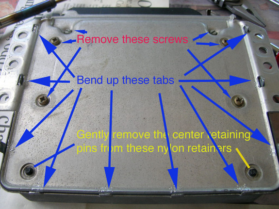
Lay the ECU on your workspace, upside down, and remove the 6 screws and the two nylon inserts in the nylon retaining clips.
Gently slide off the cover, and remove the top half as well. There will be 4 aluminum spacers that you'll want to grab and put off to the side with the screws et. al.
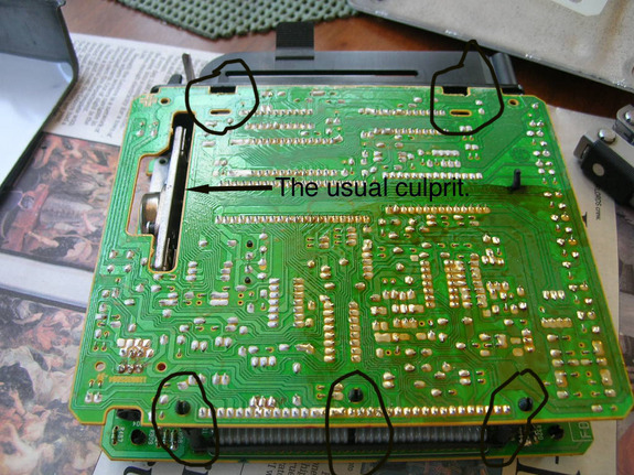
There are three nylon posts between the two boards at the rear (either side and middle of the ribbon connector). Gently pry the posts apart, and carefully disengage the top board from the large black connector (lift up the back side, gently depress the plastic clips in the holes near the black connector and it should slide out and free). Lay the whole thing open like a sandwich. A sandwich with lots of little resistors, transistors, diodes, chips, and capacitors.
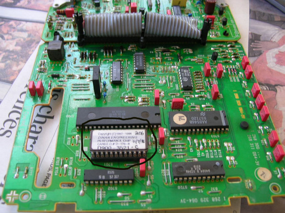
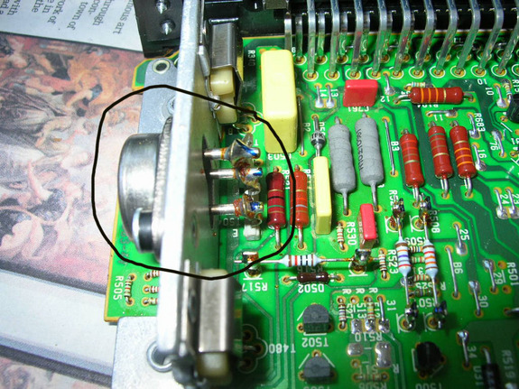
If you're looking to replace your chip, this is where it lives. Circled in the picture, it's the only removeable chip on the board. Chips on these ECU's are either 24 or 28-pin chips. This one is 24 (12 on one side). Only way to tell is to count, unless you have access to some arcane BMW parts list, in which case, why are you reading my amateur walk-through to begin with? But I digress...
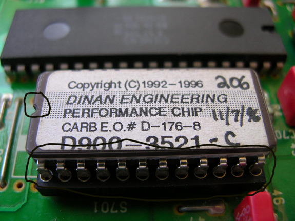
This ECU came with a Dinan performance chip. I don't notice much difference from stock, but then I don't drive in the upper RPM range much, either. Chip can be gently pried out, but pry evenly from both sides, a little at a time or you'll bend the pins. When replacing, the notched end of the chip goes on the notched end of the connector. Might want to make a mark on the board with a Sharpie just to be sure. There is also a white mark on the board outlining the chip to show which end is notched.
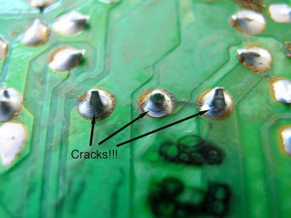
Back to the transistor pins. The largest component on the board is a large transistor mounted to a hunk of aluminum as a heat sink (to dissipate heat). Where the connectors are soldered to the board is the weak point of this ECU and the solder joints are prone to cracking. The picture on the left shows the transistor, the pic on the right shows the solder joints on the back side of the board: (the dead moth on the far left of the second image probably wasn't helping things, either - how the hell did he get in there?!!)

A close-up of those solder points reveals the problem: all three solder joints are cracked. It may not seem like much, but corrosion will build up in these cracks. A momentary loss of connection in any of these three joints will stop your engine dead. No spark, no start. Then, magically, minutes or hours later, it will start and run as if nothing were wrong. VERY frustrating problem.
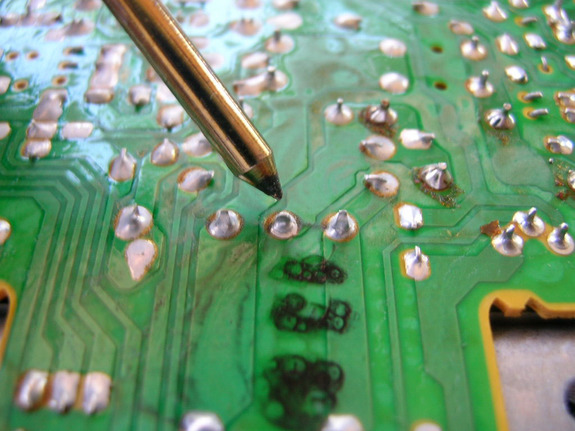
Using a small to medium tip solder iron, just touch the iron to the contacts long enough to melt the solder and remove the cracks. A "proper" repair would involve heating the solder, using a "solder sucker" or wick to remove the old solder, and re-soldering with new solder. I went halfway - heated the old and applied just a little new solder. Although these boards are pretty rugged, you do not want too hot an iron or to leave it in contact with the pins too long - you'll melt the board, spread solder to an adjoining contact, or otherwise mess up the board. The iron in the picture is just a cheap Radio Shack iron, and is about as large as you should use for this job.

That should do it - re-assembly should be easy. Make sure all pieces are snapped back together, the little aluminum spacers are in place, and the plastic sheets are between the circuit board and the outer casing. Hopefully you've solved your stalling/non-starting issue, saved some money, and learned more about your BMW all at the same time!
Happy Motoring.